

POWER SUPPLAY 13,8 Volt


Part list for 12 Amp BDX33-based power supply:
2 x 15 volt 6+ amps
2 times two MR750 (MR7510) diodes (MR750 = 6 Ampere diode) or 2 times 3 1N5401 (1N5408) diodes.
F1 = 1 Amp
F2 = 15 amp
R1 2k2 1 Watt
R2 10k
R3 1k 0.5 watt
R4,R5,R6,R7 0.1 ohm 10 watt
R8 4.7
R9 6k8
C1 two times 4700uF/35v
C2 330uF/35v
C0',C3,C4,C6,C10 100nF
C7 330uF/25v
C8 47nF
C9 47uF/25v
D1 1N5401
D2 LED
D3, D4, D5 1N4001
IC1 78L15
relay 12 volt 2x5 amp switching
3 darlington transistors: T0,T1,T2 = BDX-33 NPN TO-220 transistor
Zd 8 or 9 volt, 5 watt
P1 2k trimmer
If using a bridge rectifier (like in schematic 2) you do not need 2 x 15 volts 6 amps, but 1 x 15 volt 10+ Amps
Part list for 20 Amp BDX33-based power supply:
2 x 15 volt 12+ amps
2 times 3 MR750 (MR7510) diodes (MR750 = 6 Ampere diode) or 2 times 5 1N5401 (1N5408) diodes.
F1 = 2 Amp
F2 = 25 amp
R1 2k2 1 Watt
R2 10k
R3 1k 0.5 watt
R4,R5,R6,R7 0.1 ohm 10 watt
R8 4.7
R9 6k8
C1 22000uF/35v
C2 330uF/35v
C0',C3,C4,C6,C10 100nF
C7 330uF/25v
C8 47nF
C9 47uF/25v
D1 1N5401
D2 LED
D3, D4, D5 1N4001
IC1 7815
relay 12 volt 10 amp switching
Four darlington transistors: T0,T1,T2,T3 = BDX-33 NPN TO-220 transistor
Zd 8 or 9 volt, 5 watt
P1 2k trimmer
If using a bridge rectifier (like in schematic 2) you do not need 2 x 15 volts 12 amps, but 1 x 15 volt 20 Amps
Read more...
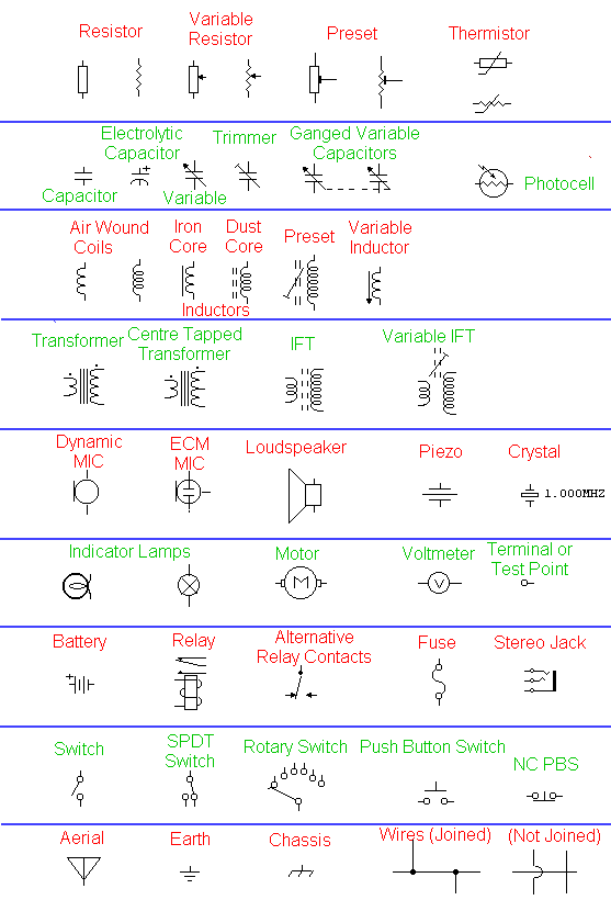
SIMBOL ELEKTRONIKA
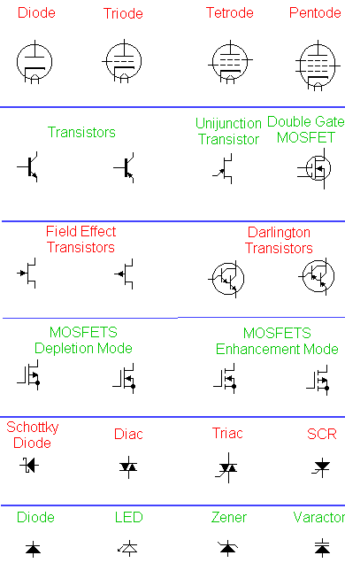
This next diagram depicts active components, the difference between active and passive is that active components require a power source to work, whereas passive components do not. The top symbols represent vacuum tube or thermionic devices. Although at one time, these were being replaced by the smaller transistor and integrated circuits, they are finding their way back into electronics for use in professional audio equipment and some radio receivers
GERBANG LOGIKA
Gerbang logika atau gerbang logik adalah suatu entitas dalam elektronika dan matematika Boolean yang mengubah satu atau beberapa masukan logik menjadi sebuah sinyal keluaran logik. Gerbang logika terutama diimplementasikan secara elektronis menggunakan dioda atau transistor, akan tetapi dapat pula dibangun menggunakan susunan komponen-komponen yang memanfaatkan sifat-sifat elektromagnetik (relay), cairan, optik dan bahkan mekanik.
Ringkasan jenis-jenis gerbang logika
| Nama | Fungsi | Lambang dalam rangkaian | Tabel kebenaran | |||||||||||||||||
|---|---|---|---|---|---|---|---|---|---|---|---|---|---|---|---|---|---|---|---|---|
| IEC 60617-12 | US-Norm | DIN 40700 (sebelum 1976) | ||||||||||||||||||
| Gerbang-AND (AND) |    |  |  |  |
| |||||||||||||||
| Gerbang-OR (OR) |   |  |  |  |
| |||||||||||||||
| Gerbang-NOT (NOT, Gerbang-komplemen, Pembalik(Inverter)) |   |  |  |  | \
| |||||||||||||||
| Gerbang-NAND (Not-AND) |    |  |  |  |
| |||||||||||||||
| Gerbang-NOR (Not-OR) |    |  |  |  |
| |||||||||||||||
| Gerbang-XOR (Antivalen, Exclusive-OR) |   |  |  |  atau  |
| |||||||||||||||
| Gerbang-XNOR (Ekuivalen, Not-Exclusive-OR) |    |  |  |  atau  |
| |||||||||||||||
Subscribe to:
Posts (Atom)
About
- ORANG PINGGIRAN
- MANUSIA YANG INGIN SELALU BERGUNA DI LINGKUNGAN SEKITARNYA,.......